
Anyone for Strowger?
The "How to Build a Strowger Exchange for Fun" Blog
I like strowger and I enjoy designing and building equipment which uses relays, selectors, regenerators etc. I started this project so that it would follow on from the satellite exchange I have built for Parkend signal box. The railway will probably never need another strowger exchange, however if I build a further exchange it can be used as my "house" exchange if not required by the DFR. It will be designed to be very flexible and to be able to fit into the DFR linked numbering network at any point.
Eventually the railway would like to extend to Cinderford, which is a long way from the present northern terminus at Parkend. The exchange will need to be suitable for installation at Cinderford and so I will refer to it as Cinderford exchange.
September 2016
I started to look around my stock of strowger spares to see what I had that could be used for Cinderford exchange. I found most of the basic items. I had a set of four banks, with the multiple still connected between them, but with the wiring away to the rear strip connections hacked off. There were three 4000 type PAX connecting circuits that could be converted to conventional final selectors, a couple of 50 outlet uniselectors to act as linefinders and as many ordinary uniselectors as I might need to act as selector and junction hunters. I had a frame for mounting nine uniselectors, a 4 position relay set shelf, fuse mountings, 20 UAX13 line circuits in two cans and hundreds of relays. Enough to start thinking about the design.
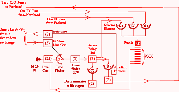
One requirement for an exchange at Cinderford would be to regenerate all calls going south as the junction line length involved to Parkend would be rather long. A call to Lydney Junction would also be further regenerated at Parkend. The regenerator will need to be incorporated in the initial relay set seized, so that all three digits will be available to send to the rest of the DFR network.
When a call is made, the access relay set is seized via a linefinder. In turn its discriminator hunter looks for and seizes a discriminator. Dial tone is returned from the discriminator. Any digit dialled is stored in a regenerator and the first digit also steps a uniselector. Strappings on the uniselector bank determine whether the call is local or junction.
On a junction call, the discriminator instructs the access relay set to use its junction hunter to find a free junction to Parkend. The regenerator then transmits the three stored digits to Parkend exchange. When all digits have been sent, the discriminator is released.
On a local call, the access relay set is instructed to use its selector hunter to find a free final selector and the discriminator is released. The last two digits will be dialled into the final. The multiple will cover 10-19, 20-29, 90 (exchange telephone), 99 (exchange test number).
Dialling 9 anywhere on the DFR network gets the call to an incoming selector hunter at Cinderford which in turn connects the incoming junction to a free final selector. Incoming junctions from Norchard and Parkend will be required.
I wanted a design that would make up initially into a two digit exchange that I could use as my house exchange, and then be extended to a three digit exchange that would integrate into the DFR network at any point. The size was set by the equipment available.
The 20 line circuits would make this a 21 line exchange, probably using levels 1 and 2 of the final selector multiple plus 99 as a test number and 90 as the exchange phone. This would be a suitable size for a DFR exchange. Paul gave me two 50 outlet uniselectors which would make ideal linefinders with the line circuits connected to outlets 10 - 29 and 00 for the exchange tele line. This meant two linefinders for outgoing traffic. Three final selectors seemed possible with the two linefinders and two incoming junctions looking to share them. This meant that I would need to provide selector hunters to distribute the traffic over the finals. This amount of equipment would form the basis of phase 1 and produce a two digit 21 line exchange.
Later, as the building of the line circuits proceeded, I realised that the exchange could easily be made to cater for a dependent (eg "trombone") exchange connected to it. Two further incoming junction line circuits would be needed to enable dependent exchange calls to obtain dial tone and be able to dial anywhere on the network. The outgoing junctions would need to come off the junction hunter banks and the discriminator would need to be able to control which junction group should be used.
October 2016
November 2016
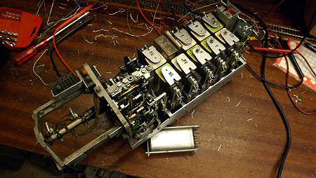
I picked the best of the PAX connecting circuit selectors that I had for conversion to a final selector. As it would require complete redesign, I simply stripped everything off the relay plate just leaving the wiring coming from the selector mechanism, wipers and test jacks for reconnection. I cleaned and lubricated the mechanism. At least it seems to be happy to step, drive and restore.
I wanted three features not available on the PAX selector. One was a transformer transmission bridge as we have found that such a bridge reduces noise on junction calls to a very small level. The next feature was the ability to return NU tone if the called number was spare. Finally I wanted the selector to be able to return dial tone when it was in use in a two digit configuration. The diagram turned out as below.
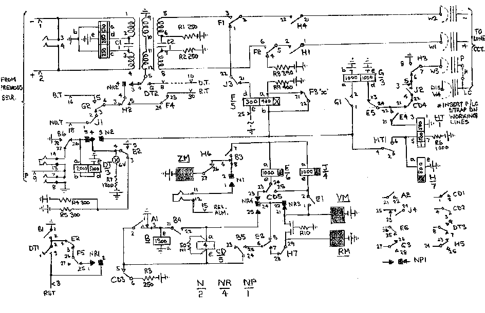

This initial selector turned out to be quite straightforward to design using as many of the relays from the PAX connecting circuit as possible. It cannot be tested completely yet, as I need ringing, tones and line circuits built to provide exactly the right conditions. Nevertheless the selector seizes, steps and tests correctly into the three P wire conditions it will find when in use. It expects to find a 1300 ohm battery if the line is free, an earth if the line is busy and a "dis" if the line is spare.
Eventually I will need to build two more of these final selectors, but one will be enough for testing and use in a two digit configuration.
December 2016

This relay set provides the relays for the two uniselector linefinders. The circuit is derived from that used in the Lydney Junction and Parkend North exchanges. The uniselectors themselves will be mounted separately on a frame, along with the selector and junction hunters. The space left in the relay set will be used for the S & Z pulse generator which provides for the timing out on PG conditions.
The diagram to which I am working is shown below :

The S & Z generator has been completed as part of the linefinder relay set. The timing is derived from charging and discharging the 470 microfarad capacitor in figure 2. When an earth appears on the S & Z start lead, relay ST operates and in turn provides an earth to the transistor circuitry. The R3/R4 potential divider also provides a -16volts supply to the transistors.
Relays P and PP are normally released. The capacitor starts to charge via the 220K resistor. Initially there is no charge on the capacitor and it takes around 160 seconds for the voltage to rise to 11.9 volts.
Until now Transistor T1 has been non conducting and the high voltage on its collector has kept T2 conducting. This has produced a voltage of around 11 volts on the T1 and T2 emitters. As soon as the capacitor voltage is 0.7 volts more than the emitter voltage, T1 conducts. This lowers its collector voltage which in turn switches T2 off. As T1 has more resistance in its collector circuit than T2, the drop in current in the 1200 ohm emitter resistor lowers the emitter voltage to around 5 volts. The capacitor starts to discharge through the base emitter junction.
When the capacitor voltage reduces to around 5.7 volts, T1 switches off and the rise in collector voltage turns T2 back on.
This sequence can continue. T1 is non conducting for around 120 seconds for all subsequent pulses as the capacitor voltage starts at 5 volts rather than zero. T1 is conducting for less than a second.
T3 is normally non conducting as its base is virtually at earth potential whilst T1 is non conducting. Relays P and PP are therefore normally released.
When T1 conducts (ie for less than a second every 120 seconds), current flows in the 1.8K collector resistor and the subsequent voltage rise turns T3 on. This causes P and PP to operate while T1 is on.
Contact PP1 removes the capacitor charging circuit and replaces it with a 2.7K discharge circuit to ensure that T1 is turned off securely. When T1 and T3 are off, the relays release and PP1 reconnects the charge circuit for the next timing period.

The relay circuitry is simple. With ST operated, relay P operates for about a second every two minutes. This pulses the type 4 uniselector. When the uniselector has taken 12 steps, P2 operates relay PA and in turn relays PB and PC are also operated.
When P2 restores, relays PA, PB and PC restore slowly in sequence. When PA releases, a Z pulse is generated during the release lag of PB. This is followed by an S pulse during the release lag of PC.
Referring to the line finder diagram, you can see that relay S will operate to the first S pulse that occurs after the call has commenced and relay HR is operated, any Z pulse will be ignored until after relay S is operated. The S pulse may arrive any when between zero seconds and around 24 minutes. The Z pulse occurs 24 minutes after the S pulse and this causes the release of relay H, as the Z pulse winding is differentially connected. Relay H then releases relay HR which simultaneously disconnects all the relay H windings, thus preventing relay H from re-operating. Releasing H and HR releases the call and the caller's loop is left holding relay P only.
This is not like the usual PG system which only operates if the call is not connected. This system operates on any call and will therefore cut off a call after the time out period of around 24 to 48 minutes.

It's that period between Christmas and New Year. Not a lot to do and a garage/workshop that is too cold to do it in. I have moved into the kitchen with the boring job of doing the wiring of the 20 line circuits. I started by stripping out all wiring that was wrong for the job. This left quite a bit of wiring in situ. Currently it is plate wiring that I am trying to get up enough interest in. I'm glad it's not a 100 line exchange. Then I will attach the cabling that will go away to the final multiple (3 wires) and the linefinder bank (5 wires). That is 160 wires sprouting away from the relays to be formed around the rack and terminated.
January 2017

This is the diagram I am working to with regard to the line circuits. They started life as UAX13 equipment but have had to be considerably modified to work to the proposed uniselector linefinders. I am providing twenty of these for normal lines, but there will be a further line circuit built later to cater for the 90 exchange telephone, plus a 99 test number circuit and two incoming only line circuits for any incoming junctions that need to dial the complete three digit number into the exchange..
February 2017

The plate wiring has been completed for the twenty line circuits and ten circuits now have rack wiring connected. If only I had the rack constructed. Each line circuit has three wires going away to the final selector multiple and five wires going to the linefinder multiple. It's getting quite complex.

The picture shows the basic 20 line circuits with the wiring complete and ready to be installed in a rack.
March 2017

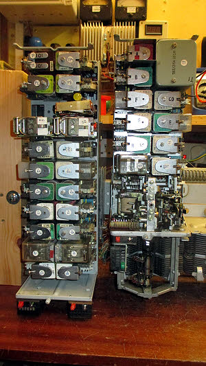
This miscellaneous relay set on the right hand side covers the following facilities :
At the top there are two incoming junction circuits. These have no connections to the final selector multiple but do appear on the linefinder banks. These circuits cater for any incoming junctions that will need to hear dial tone and dial all three digits eg from a dependent tandem exchange.
Below that there is a conventional line circuit that will be used for the 90 exchange telephone.
Opposite that there is the test number 99 circuit which has a connection to the final selector multiple only
At the bottom (plus the odd relay at the top of the set) are the alarm relays catering for fuse alarm, release alarm, PG alarm, charge fail alarm and low volts alarm.
The three tag strips temporarily mounted outboard of the relay set provide a delay in the release alarm circuit, a 35 volt stabilised supply for the low voltage circuit, the low voltage detector and series resistors for the alarm LEDs which will be plugged into the test jacks on the front of the set.
The circuits have been designed and the relays built, adjusted and mounted, and wiring has begun.

Two circuits have been provided for incoming junctions from a dependent exchange. These circuits will return dial tone on the junctions and will require all three digits to be dialled.
The circuits above provide an additional (21st) line circuit for 90, the exchange line phone and a 99 test number circuit.

The alarm circuits provide facilities for fuse alarms, release alarms (delayed by around 10 seconds by the slow charge of the 470 microfarad capacitor in the RAR relay circuit), charge fail alarm and a PG alarm. The PG alarm will operate when a linefinder finally times out on any call after around 45 minutes. The call is cut off and the user will need to redial. There is also a low voltage circuit which measures the difference between the exchange voltage and a stabilised voltage. It has two pots, one of which sets the actual voltages which will operate relay LV and a second which alters the range between operating and resetting when the voltage rises again.
April 2017
I have built a selector, two sets of line circuits, a miscellaneous relay set and a linefinder relay set. Some of these have hundreds of wires sprouting from them. The wires are doing their best to either tangle themselves up or wrap themselves around my foot as I move about my garage. I have little room in the garage as it still houses the exchange meant for Parkend Signal Box. It should have have moved out eighteen months ago but it now seems likely that it will spend the rest of the year waiting for Parkend Box to be ready for it. It's doing a nice job as a house exchange though.
I need to build a rack to house the equipment I have already constructed. I have decided that it is likely to spend the rest of its life here as the Cinderford extension will probably happen after I have departed. My rather nice garden shed will be a good home for it, though the height available will mean that I will have to have two short racks. The first rack though will house sufficient equipment for it to act as a two digit house exchange.
The following pictures show the short rack that I have built using wood. It will house the power equipment, the ringer, alarms, line circuits, 50 point linefinders, four two digit selectors (4000 type), and selector and junction hunters.
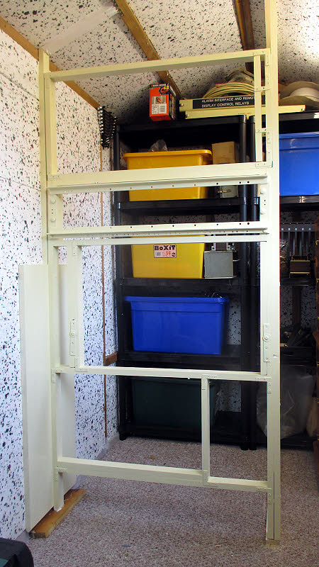 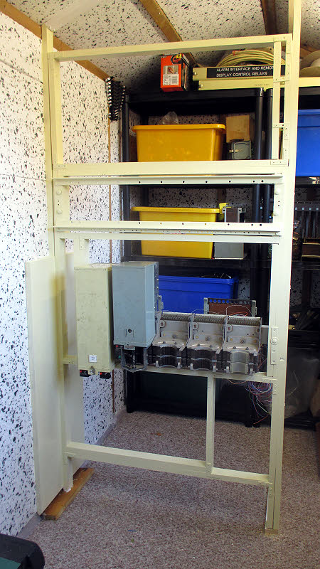
The first picture is of the basic wooden rack, the second picture has the selector shelf fitted. The relay set contains the two linefinder control relays plus the PG alarm time out equipment.
May 2017
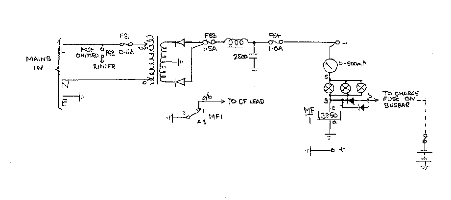
This month has been spent on the power unit, the fuse arrangements and the ringer.
 
Just as I was wondering how to mount a ringer 2A, Robert Staines, one of our ex BT colleagues asked if I had any need for the ringer mounting from a UAX13. Ideal of course and just the right size.
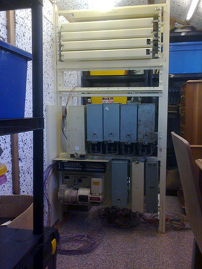
This is the state of the rack at the end of May. The three selectors on the right of the shelf are as yet not wired, only the left hand selector is a worker. The cans at the top of the rack will hold the relays for the selector and junction hunters etc.
June/July 2017

June and July have not been very productive due to holidays and other considerations. However I have been lacing out the wiring and did get the line circuits connected to the final selector multiple.
Then I turned my attention to the two linefinder uniselectors. They were both unused and expected to be trouble free after a bit of lubrication. One was fine but the other ran faster than I have ever seen a uniselector go. It arced and sparked at the interrupters and finally burnt out the relay contact controlling the magnet. That was fun, changing the relay contact pile. Luckily I could find an identical set of contacts. Then I checked the magnet resistance to find that I had an 18 ohm coil. I guess it would be used on a 24 volt supply in a PAX or set of traffic lights. Replacing the coil with a 75 ohm type did the trick. The uniselectors are now mounted and running well under the control of the linefinder relay set.
August 2017

This photo shows the wiring from the line circuits laced out ready to terminate on the uniselector banks.
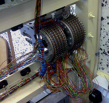 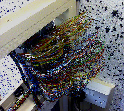
The linefinder multiple terminated, thank goodness. Not quite a factory standard job though.
I did some testing of the linefinders and the line circuits as I terminated but I cannot do a proper test as currently I can only temporarily connect one of the finders to the only final selector I have at present. I suspect that faults exist but it will be simpler to test and find them if I either build a second final to connect to the second linefinder or build the two local selector hunters which will distribute the calls from the two linefinders over up to four finals. I have sorted the uniselectors to be used for the hunters, cleaned, dewired and tested them. That's the way I propose to go eventually. However to make testing easier and earlier I have now built a second final selector which can be connected to the second line finder to make a simple 21 line exchange..
September 2017
The wiring of the linefinders and finals to the IDF has been completed and the two connected together by jumpers. It should start to work now, and it does try, but there are some tricky faults to be found now that all the bits have been put together.
The faults have been sorted out, and the house wiring has been extended to the exchange. Telephones around the house have been transferred to the new exchange so that the "Brought into Service" date BIS is September 22 2017. There remains plenty to do on the exchange as all I have at present is the two digit switching part of the proposal working. So now it's on to extension one which is planned to have further final selectors built and selector hunters installed to distribute calls over the four finals. Later, extension two will concern itself with the discriminating features required for the equipment to be able to be integrated any where into the DFR linked numbering scheme.
 |
Page provided by John Bathgate
This page was last updated on
23rd September 2017 |
|